
 English
 Español
 Português
 Pусский




Why Does an Electric Actuator Overheat During Operation?
Learn how cycling, valve resistance, electrical conditions and the installa...



Torque & Flange: 50 – 5,000 N·m | Standard ISO 5211 (F05 – F25) Control Options: On-Off, 4–20mA Modulating (RPC) & Smart Modbus RTU (RS485) Protection & Enclosure: IP67 / IP68 & Exd IIB T4| CE, SIL3, ATEX Factory Guarantee: 18-Month Factory Warranty | 100% Individual Torque Tested & OEM Supported
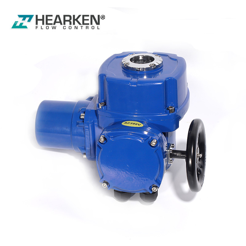
The Hearken Flow HQ Series electric quarter-turn actuators are designed for high-performance automated control of butterfly valves, ball valves, plug valves, and dampers in industrial applications, offering a torque range from 50 N·m to 5,000 N·m. The HQ series uses a rugged and durable ADC12 die-cast aluminum housing and is equipped with a hardened 40Cr self-locking worm gear drive mechanism, ensuring exceptional durability and impact resistance. HQ actuators are designed with mounting interfaces compliant with ISO 5211 and a clutch-free manual override handwheel, supporting both direct installation on quarter-turn valves and convenient emergency operation without the need for a manual clutch handle. The HQ series is available in a variety of configurations, including on/off, 4–20 mA proportional control, and intelligent Modbus RTU bus control. With an IP67/IP68 protection rating and Exd IIB T4 explosion-proof certification, it provides valve manufacturers and distributors worldwide with a highly reliable and cost-effective automation solution.
 |
 |
 |
|
Feature & Technical Spec |
Engineering & Buyer Advantage |
|
|
Torque Range: 50 – 5,000 N·m HQ Series electric quarter turn actuator models range from the HQ005 (50 N·m) to the HQ500 (5,000 N·m), with consistent operating speeds (15 to 60 seconds for a 90° stroke). |
You can use the same actuator series to automate the entire range of valves—from DN32 ball valves to DN700 butterfly valves and DN1600 aeration valves—thereby significantly reducing procurement and inventory costs. |
|
|
Standard ISO 5211 Mounting & Interchangeable Drive Sleeves Standardized mounting flange interfaces are available in sizes F05 through F25, equipped with modular drive inserts (including double-sided holes, octagonal holes, or keyway types). |
The HQ Series electric quarter-turn actuators can be mounted directly onto standard valve top flanges without the need for expensive custom brackets or external couplings, thereby reducing OEM assembly time by up to 60%. |
|
|
Clutchless Manual Override Handwheel Our actuators are equipped with an integrated handwheel mechanism featuring a high reduction ratio (60:1 to 348:1), enabling automatic switching between electric and manual modes without the need for a manual clutch lever or handle. |
During a power outage, you can easily open or close large valves manually. When power is restored, the HQ Series electric quarter-turn actuators automatically resume electric operation without the risk of mechanical damage or personal injury. |
|
|
Rugged and Durable ADC12 Die-Cast Aluminum Enclosure Hearken Flow HQ actuators are manufactured from precision die-cast ADC12 aluminum alloy, with the housing surface treated with a high-temperature-cured, electrostatic anti-corrosion powder coating. |
Our HQ actuator's enclosure is both ultra-lightweight and sturdy, which not only greatly reduces international air or sea freight costs and facilitates installation by one person, but also avoids excessive bending stress on small valve pipelines. |
|
|
Hardened 40Cr Alloy Steel Worm Gear Drive Mechanism Internal transmission uses heat-treated, precision-machined 40Cr alloy steel worm shafts and worm gears with inherent self-locking function. |
When subjected to pressure fluctuations, vibrations, and dynamic fluid impacts in pipelines, the valve maintains its position securely without reverse drive or position drift, ensuring exceptional wear resistance and long-term mechanical reliability under high-intensity cyclic operating conditions. |
|
|
Dual-travel Limit Switches and ±5° Mechanical Limit Stops The HQ Series electric actuators are equipped with four standard built-in micro switches (LSO1/LSO2 for open limit and feedback, LSC1/LSC2 for closed limit and feedback), as well as externally adjustable mechanical limit bolts with locking nuts. |
Our actuator can perform precise calibration of the valve’s 0° and 90° positions, thereby avoiding seat leakage and preventing actuator stroke overshoot. |
|
|
Built-in Torque Overload Protection Mechanism (TSO / TSC) The integrated mechanical torque switch continuously monitors the real-time drive torque during valve opening and closing. |
If the valve becomes jammed due to debris in the pipeline or scale buildup, the system automatically cuts off power to the motor, thereby protecting the valve stem, valve disc, and internal gearbox from permanent structural damage. |
|
|
Class F Heavy-Duty Motor with Thermal Protection Our actuators use high-starting-torque motors with Class F insulation and an S2 duty cycle (i.e., capable of continuous operation for 10–15 minutes at rated load), and feature a built-in thermal protection device (TH switch). |
Ensures reliable operation under high-frequency regulation conditions and prevents failures or degradation of motor winding insulation caused by overheating. |
|
|
Multi-Voltage Power Supply Standard power supply: Three-phase AC 380 V (50/60 Hz) or single-phase AC 220 V (50/60 Hz). Additional voltage options are available: AC 24 V, AC 110 V, AC 440 V, AC 660 V, and DC 12 V / DC 24 V / DC 220 V. |
Whether in municipal water supply systems, marine applications, off-grid solar systems (DC 24V), or heavy-duty industrial facilities—across a wide range of global applications—power can be supplied directly without the need for an external step-down transformer. |
|
|
Control Modules: Switching Type, 4–20 mA Control Type, and Non-Intrusive Smart Type HQ Series electric quarter-turn actuator supports standard switch control (with passive dry-contact feedback), smart proportional control (4–20 mA / 0–10 V input and output), and smart integrated control with local/remote push-button operation. |
It can be easily adapted to basic on/off fluid piping systems and also meets the requirements of high-precision automated chemical or HVAC process control loops (with a control sensitivity of up to 0.1%). |
|
|
Smart Modbus RTU (RS485) Bus Control & 16-Bit Diagnostics Uses the standard two-wire half-duplex Modbus RTU protocol and features 2 kV optocoupler signal isolation. The 16-bit status register provides detailed fault codes (E1 through E16: covering faults such as motor stalling, phase loss, overtemperature, overtorsion, and signal interruption). |
You can remotely read real-time valve positions and diagnose faults from the control room without having to remove the actuator enclosure. |
|
|
IP67/IP68 Weatherproof and Exd IIB T4 Explosion-Proof Enclosure We use an O-ring seal design with a protection rating of IP65/IP67 (optional IP68 submersion rating); certified for use in explosive gas environments of Class IIA/IIB, Groups T1–T4; Operating temperature range: -20°C to +60°C (optional: -40°C to +70°C). |
Certified for use in harsh environments and hazardous areas; helps EPC contractors and distributors comply with regulations when bidding on projects such as water treatment plants, outdoor refineries, and hazardous chemical pipeline projects. |
|
|
Direct Factory Supply, OEM Customization & 18-Month Warranty Enjoy direct-from-manufacturer pricing, backed by ISO 9001, CE, ATEX, RoHS, and SIL 3 quality system certifications. All HQ series electric quarter-turn actuators are passed 100% torque and pressure testing before shipment and come with an 18-month warranty. |
You’ll receive wholesale discounts through direct factory supply, private-label customization services (such as laser-engraved logos and custom colors), and reliable replacement support, allowing you to maximize your channel profit margins. |
|
Problem |
Possible Cause |
How do we solve it? |
|
Motor does not run or respond to open/close commands |
The power line is disconnected, there is a fault in the external control circuit, or the internal thermal protection switch (TH) has tripped. |
We need to check the main power cable connections and the supply voltage. Check the wiring of the external control circuit connected to terminals 4, 5, and 6. If the motor has overheated due to continuous cyclic operation, wait for it to cool down so that the built-in thermal protection switch can reset automatically. |
|
The output shaft rotates in the opposite direction of the command signal. |
The phase sequence of the three-phase AC 380 V power supply wiring is reversed. |
We need to press the “Stop” button immediately to avoid the valve from seizing. Disconnect the three-phase power supply, swap any two of the three phases (U, V, W) at the terminal block, and then retest the rotation direction. |
|
The motor stops during operation (torque trip / Modbus error codes E11, E12) |
The valve disc or ball is jammed by debris in the pipeline or severe scale buildup, or the internal torque control switch (TSO/TSC) has been triggered. |
Manually turn the clutchless handwheel to check whether the valve rotates smoothly. Remove any debris from the pipeline obstructing the valve. If the valve’s torque requirements match the HQ actuator’s rated parameters, check and calibrate the torque switch settings (TSO for the open direction, TSC for the closed direction). |
|
Motor overheating or frequent thermal overload trips (Modbus error codes E8, E10) |
Continuous operating time exceeds the rated value for the S2 10-minute duty cycle, a phase is missing from the three-phase power supply, or the HQ actuator was selected with insufficient torque. |
We need to stop operation immediately and allow the motor to cool. Check the three-phase line voltage and resolve the phase loss issue. Verify the valve’s actual operating torque against the HQ selection table to ensure there is a sufficient safety margin. |
|
Actuator does not stop at end position (Over-travel) or feedback lamp fails |
The limit cam of the microswitch is loose or improperly adjusted, or the mechanical limit bolt is set incorrectly. |
Manually operate the valve to the fully closed position, loosen the output shaft cam screw, and turn the closing cam clockwise until it engages microswitch LSC1/LSC2 and emits a “click” sound; then tighten the screw. Repeat the above steps for the open position (LSO1/LSO2). Adjust the external mechanical limit bolts to ensure there is a 1–2-turn buffer after the microswitch actuates. |
|
Open & Close Command Conflict (Modbus E7) at the same time |
A wiring fault in the external PLC or relay output has caused the remote “On” and “Off” control signals to be activated at the same time. |
We need to check the logic of the external control system and the wiring at terminals 4, 5, and 6. Ensure the remote interlock relay or PLC program prevents the simultaneous issuance of “On” and “Off” commands. |
|
4–20mA control signal is lost or hunting (Modbus E6) |
The analog control loop cable is disconnected, the wiring polarity is reversed, or there is severe line interference. |
Use a multimeter to check the continuity and polarity of the 4–20 mA input/output wiring loop. Ensure that shielded twisted-pair cable is used and that it is properly grounded at a single point to avoid electromagnetic noise. |
|
Position Acquisition Error or Zero/Range Calibration Failure (Modbus E2, E3) |
The calibrated angle difference between the fully closed and fully open positions is too small, or the feedback potentiometer has been rotated beyond its valid electrical travel range. |
Recalibrate the 0% (fully closed) and 100% (fully open) travel limits. Fine-tune the position of the feedback potentiometer to keep the entire angular travel within the valid resistance range. |
|
Limit Switch & Torque Switch Logic Mismatch Alarm (Modbus E14) |
The wiring of the limit switch’s microswitch conflicts with the torque switch’s logic (for example, the torque switch contact for the “close” direction is triggered during “open” operation). |
Check the microswitch’s terminals and swap the limit switch’s wiring, or adjust the internal software masking parameters via the Modbus command register. |
 |
 |
 |
Mounting Orientation & Gearbox Lubrication
Keep the motor shaft as level as possible when installing the actuator; at the same time, the electrical compartment cover should be in a horizontal position or facing upward to facilitate the distribution of internal grease and commissioning operations.
The hardened 40Cr worm gear set and bearings have been filled with high-quality industrial gear grease before shipment. Under normal operating conditions, periodic grease replenishment is not required; however, during major factory overhauls (every 18 to 24 months), the condition of the gear grease should be inspected.
Weatherproof Enclosure and Cable Gland Sealing
Be sure to evenly tighten all wiring compartment cover screws (Part No. 26/49) on the ADC12 die-cast enclosure to maintain IP67/IP68-rated weatherproof sealing.
At the conduit entry points, use certified explosion-proof cable glands or waterproof cable glands with the appropriate IP rating. For unused cable entry points, seal them with metal threaded blind plugs to avoid moisture or dust from entering.
Travel Cams & Mechanical Limit Stopper Check
Regularly inspect and verify that the bolts on the mechanical limit stops on both the open and closed sides are securely fastened with their respective hex lock nuts.
Inspect the micro-switch cam set screw on the center output shaft (Part No. 41) to ensure that vibrations caused by high-speed piping have not caused the cam to shift out of position.
Electrical Terminals and Signal Testing
Inspect the terminal block (terminals 1–20) annually to confirm all wire connections are secure and free from electrochemical corrosion.
If an HQ Series electric quarter-turn actuator has been stored in a high-humidity environment (relative humidity ≤ 95%) before startup, use a 500 V megohmmeter to measure the insulation resistance of the motor windings (the resistance must be greater than 20 MΩ).


|
Model Spec |
Output torque |
Output speed |
Max stem diameter |
Manual speed ratio |
Motor power |
Rated current |
Reference weight |
|
HQ005 |
50 |
1 |
19 |
60 |
45 |
0.35 |
8.5 |
|
HQ010 |
100 |
1 |
19 |
60 |
60 |
0.48 |
8.6 |
|
HQ015 |
150 |
1 |
19 |
60 |
75 |
0.55 |
8.7 |
|
HQ020 |
200 |
1 |
28 |
90 |
90 |
0.65 |
12.7 |
|
HQ030 |
300 |
1 |
28 |
90 |
120 |
0.75 |
12.7 |
|
HQ040 |
400 |
1 |
28 |
90 |
150 |
0.85 |
13 |
|
HQ060 |
600 |
1 |
38 |
87 |
180 |
0.95 |
21 |
|
HQ120 |
1200 |
1 |
38 |
87 |
250 |
1.3 |
21 |
|
HQ180 |
1800 |
1 |
38 |
87 |
370 |
1.7 |
23 |
|
HQ300 |
3000 |
0.5 |
55 |
348 |
370 |
1.7 |
35 |
|
HQ500 |
5000 |
0.5 |
55 |
348 |
550 |
2.5 |
35 |

|
Model |
B1 |
B2 |
H |
H1 |
H2 |
L |
L1 |
D |
|
HQ005/015 |
68 |
114 |
156 |
270 |
73 |
250 |
157 |
140 |
|
HQ020/040 |
91 |
157 |
191 |
273 |
103 |
332 |
208 |
160 |
|
HQ060/180 |
143 |
203 |
227 |
309 |
126 |
424 |
232 |
250 |
|
HQ300/500 |
143 |
203 |
291 |
373 |
190 |
424 |
232 |
250 |
Selecting the ideal electric actuator ensures optimal valve automation performance, prevents premature motor wear, and prevents the valve stem from shearing. Please follow the four-step selection process below to configure the mount HQ Series electric quarter-turn actuator model for you.
Calculate the maximum starting torque (seat-lift torque) of the valve under the operating pressure differential, and apply the industry-standard safety factor (generally 1.2 to 1.3 for clean liquids; 1.5 or higher for slurries, dry gases, or high-viscosity media).
Match the calculated torque requirement with the rated torque of the HQ Series:
|
Actuator Model |
Rated Torque (N·m) |
Soft-Seal Butterfly Valve |
Hard-Seal Butterfly Valve |
Ball Valve (Standard) |
Aeration / Damper Valve |
|
HQ005 |
50 N·m |
≤ DN65 (2-1/2") |
≤ DN40 (1-1/2") |
≤ DN32 (1-1/4") |
≤ DN100 (4") |
|
HQ010 |
100 N·m |
DN80 – DN100 (3" – 4") |
DN40 – DN65 (1-1/2" – 2-1/2") |
DN40 – DN50 (1-1/2" – 2") |
DN100 – DN200 (4" – 8") |
|
HQ015 |
150 N·m |
DN125 – DN150 (5" – 6") |
DN80 – DN125 (3" – 5") |
DN65 – DN80 (2-1/2" – 3") |
DN250 – DN300 (10" – 12") |
|
HQ020 |
200 N·m |
DN150 – DN200 (6" – 8") |
DN100 – DN125 (4" – 5") |
DN65 – DN80 (2-1/2" – 3") |
DN250 – DN350 (10" – 14") |
|
HQ030 |
300 N·m |
DN150 – DN200 (6" – 8") |
DN125 – DN150 (5" – 6") |
DN80 – DN100 (3" – 4") |
DN300 – DN400 (12" – 16") |
|
HQ040 |
400 N·m |
DN200 – DN250 (8" – 10") |
DN150 – DN200 (6" – 8") |
DN100 – DN125 (4" – 5") |
DN400 – DN500 (16" – 20") |
|
HQ060 |
600 N·m |
DN250 – DN300 (10" – 12") |
DN200 – DN250 (8" – 10") |
DN125 – DN150 (5" – 6") |
DN500 – DN600 (20" – 24") |
|
HQ120 |
1200 N·m |
DN300 – DN350 (12" – 14") |
DN250 – DN300 (10" – 12") |
DN150 – DN200 (6" – 8") |
DN600 – DN800 (24" – 32") |
|
HQ180 |
1800 N·m |
DN400 – DN450 (16" – 18") |
DN300 – DN400 (12" – 16") |
DN200 – DN250 (8" – 10") |
DN800 – DN1000 (32" – 40") |
|
HQ300 |
3000 N·m |
DN500 – DN600 (20" – 24") |
DN400 – DN450 (16" – 18") |
DN250 – DN300 (10" – 12") |
DN1000 – DN1200 (40" – 48") |
|
HQ500 |
5000 N·m |
DN600 – DN700 (24" – 28") |
DN450 – DN500 (18" – 20") |
DN300 – DN350 (12" – 14") |
DN1200 – DN1600 (48" – 64") |
We need to check the valve’s top mounting flange and stem connection to ensure direct mounting without brackets:
Mounting flange dimensions: Compliant with ISO 5211 standard specifications (F05, F07, F10, F12, F14, F16, up to F25).
Drive Output Sleeve/Valve Stem Types:
Double-ended (star-shaped)/octagonal valve stems: Sizes range from 17×17 mm (HQ005–HQ015) to 47×47 mm (HQ300–HQ500).
Round Shafts with Keyways: Supported stem diameters range from Φ19 mm to Φ63 mm.
Custom Machining: Hearken Flow offers custom-machined drive sleeves to accommodate flat-end, double-D, or non-standard OEM stems.
Select the appropriate motor voltage and enclosure protection rating based on the power grid and environmental conditions:
Power Supply Voltage:
Industrial Standard: Three-phase AC 380 V (50/60 Hz) or single-phase AC 220 V (50/60 Hz).
Optional Power Supplies: Single-phase AC110V, AC24V, AC440V, AC660V, or DC12V / DC24V / DC220V.
Enclosure Protection and Ambient Temperature:
Industrial Standard (Weather-Resistant): Protection rating IP65/IP67, ambient temperature -20°C to +60°C.
Hazardous Locations (Explosion-Proof): Exd IIB T4 explosion-proof certification, suitable for explosive gas environments of Class IIA and IIB, Groups T1–T4.
Extreme Environment Options: IP68 submersible-grade protection or high/low-temperature configurations ranging from -40°C to +70°C.
Ensure the HQ series actuator’s control mode and how it will be integrated into the plant control network:
Standard ON/OFF Switch Type: Controlled by an external relay (terminals 4, 5, 6) and equipped with a passive dry-contact microswitch to indicate the on/off position.
Smart Proportional Modulating Type (4–20mA): HQ series electric quarter-turn actuators use a built-in microprocessor that accepts a 4–20 mA (or 0–10 V) continuous control signal and outputs a 4–20 mA proportional position feedback signal.
Smart Modbus RTU Bus Control (RS-485): Features optically isolated two-wire RS-485 communication, supporting remote digital setpoint control, actual position monitoring, and comprehensive 14-bit fault diagnostics (E1 to E14).
Smart Integral Type with Local Control: Features a “push-to-run” local control button and a local/remote selector switch on the housing, allowing for commissioning without extra tools.
Q1: What flange standards does the HQ series support? Can flanges be customized for specific valves?
A: The HQ series explosion-proof electric quarter turn actuator complies with the ISO 5211 standard and supports top flange sizes ranging from F05 to F25. Most models come standard with dual flange holes (e.g., F05/F07, F07/F10, F10/F12, F12/F14/F16). For special valve connection requirements—such as custom F12/F16 on large-size models like the HQ180—we offer customization services.
Q2: How do HQ actuators connect to different types of valve stems (square, octagonal, and round with a key)?
A: The base of the HQ actuator is equipped with a standardized square drive and supports interchangeable output drive sleeves. As long as the valve center and pitch circle diameter (PCD) meet the requirements of the HQ actuator base, various valve stems can be accommodated by using square reducer sleeves, octagonal sleeves, or custom-machined keyed round sleeves.
Q3: What power supply voltages are available? Is there an additional charge for non-standard voltages?
A: Standard power supply includes three-phase AC380V and single-phase AC220V. We also offer AC110V and AC415V voltage options (both compatible with 50Hz and 60Hz power grids) at no additional cost. DC options (24VDC / 12VDC) are available upon request and incur a modest surcharge due to specialized DC motor winding costs.
Q4: What is the maximum torque available with the 24 VDC power supply?
A: The 24 VDC motor supports models up to HQ120 (1,200 N·m). For torque requirements higher than 1,200 N·m (HQ180 to HQ500 models), a three-phase AC power supply (AC380V / AC415V) is required to provide the torque needed to start the motor.
Q5: What is the difference in rated current between the 220 VAC single-phase model and the 380 VAC three-phase model?
A: The motors have the same output power for both voltage specifications. However, in 220 VAC single-phase operation, the rated current is approximately twice that of the 380 VAC three-phase model.
Q6: Can the 90° operating stroke time be accelerated (e.g., to 15 seconds)?
A: The standard operating times range from 15 to 60 seconds, depending on the model specifications. For the HQ005, HQ010, and HQ020 (380 VAC) models, the 15-second high-speed gear configuration is optional. For larger models (HQ060 through HQ500), the operating time can be shortened by adjusting the gear ratio; however, increasing the output speed will reduce the effective output torque to approximately 70% of the standard rated value.
Q7: Do all HQ series models include built-in torque overload switches (TSO/TSC)?
A: HQ020 through HQ500 incorporate mechanical torque switches (TSO for the open direction and TSC for the closed direction) to protect the valve stem from damage caused by excessive torque. HQ005 through HQ015 rely on travel-limit microswitches and internal motor thermal protection (TH switch) for protection.
Q8: What are the standard cable entry dimensions? Can they be converted to 1/2" NPT?
A: All HQ Series actuators come standard with two M25×1.5 threaded cable entry ports, compatible with cables up to 18 mm in outer diameter. For North American or international EPC projects requiring 1/2“ NPT or 3/4” NPT conduit connections, metal threaded adapters are available.
Q9: What is the standard enclosure protection rating? Is explosion-proof protection available?
A: The standard enclosure protection rating for the HQ Series is IP67 (weather-resistant), making it suitable for general, non-hazardous industrial applications (IP68 submersible-grade protection is also available as an option). For hazardous areas, a certified Exd IIB T4 explosion-proof is available, suitable for explosive gas atmospheres classified as IIA and IIB, temperature classes T1–T4. Both standard and flameproof models feature a heavy-duty ADC12 die-cast aluminum housing with a high-temperature, corrosion-resistant powder coating.
Q10: What working temperature range is supported by the HQ series electric quarter-turn actuator?
A: The standard working temperature range is -20°C to +60°C. For installations in cold climates or high-temperature industrial environments, special internal seals and low-temperature lubricants can be selected to extend the operating temperature range to -40°C to +70°C.
Q11: For marine or corrosive applications, can the manual handwheel be upgraded to SS316L stainless steel?
A: Yes. Although the standard handwheel is made of heavy-duty cast aluminum with an epoxy resin coating, an upgraded version made of SS316L stainless steel with an external protective coating is available for highly corrosive chemical or marine environments.
Q12: Does the HQ series feature a mechanical locking mechanism?
A: Yes. The 40Cr alloy steel worm gear drive provides inherent mechanical self-lockingto avoid back-driving from pipeline pressure. In addition, the manual handwheel is equipped with a reliable mechanical locking mechanism to prevent accidental rotation during maintenance.
Q13: What are your warranty coverage and quality inspection procedures?
A: Every HQ Series electric actuator is covered by an 18-month manufacturer’s warranty starting from the date of shipment (bill of lading date), which covers defects in materials and workmanship. Before shipment, all actuators undergo a 100% comprehensive routine inspection in accordance with the ISO 9001 quality management system. The inspection includes full-load torque testing, high-voltage dielectric strength testing, travel limit switch calibration, and verification of the protective enclosure’s seal integrity.
Q14: Do you offer OEM private labeling and custom colors for valve manufacturers?
A: Yes. We provide comprehensive OEM/ODM services for valve manufacturers and distributors, including powder coating of valve bodies in custom RAL/Pantone colors, nameplates featuring your company’s logo, custom wiring diagrams, and specialized packaging.
2026
/
Learn how cycling, valve resistance, electrical conditions and the installa...

2026
/
Check mounting, air supply, valve travel and position feedback before putti...
2026
/
Learn why pneumatic actuators lose air pressure, where leaks occur, and wha...
2026
/
Industrial automation relies on precise motion control to regulate the flow...
GET A QUOTE