
 English
 Español
 Português
 Pусский


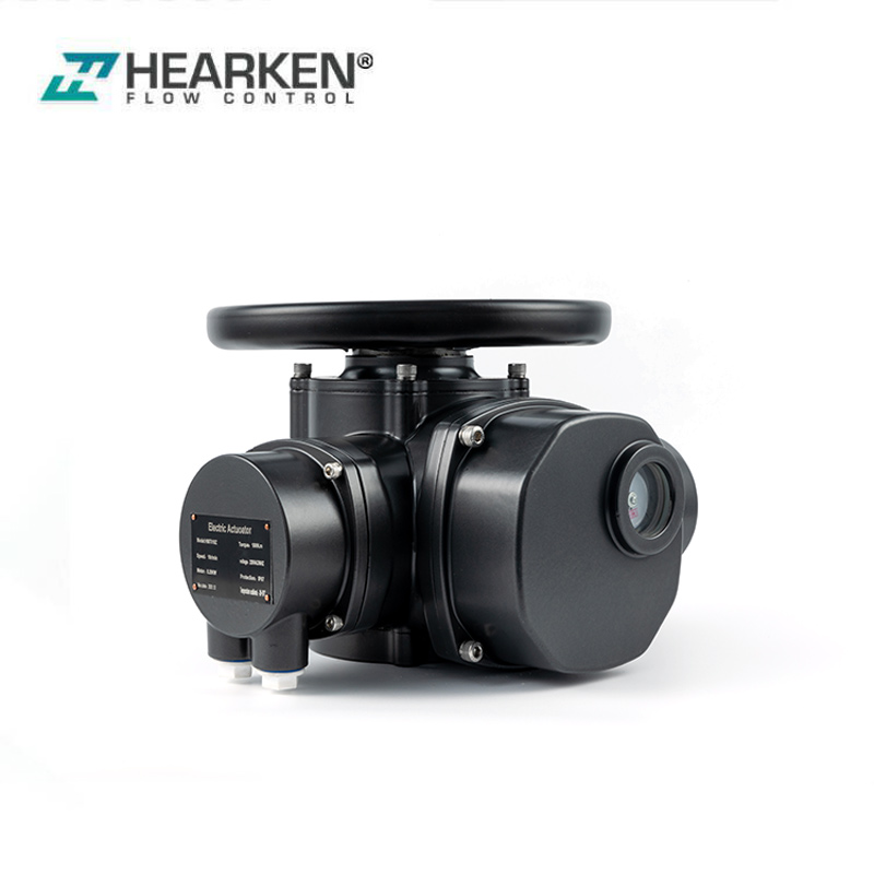
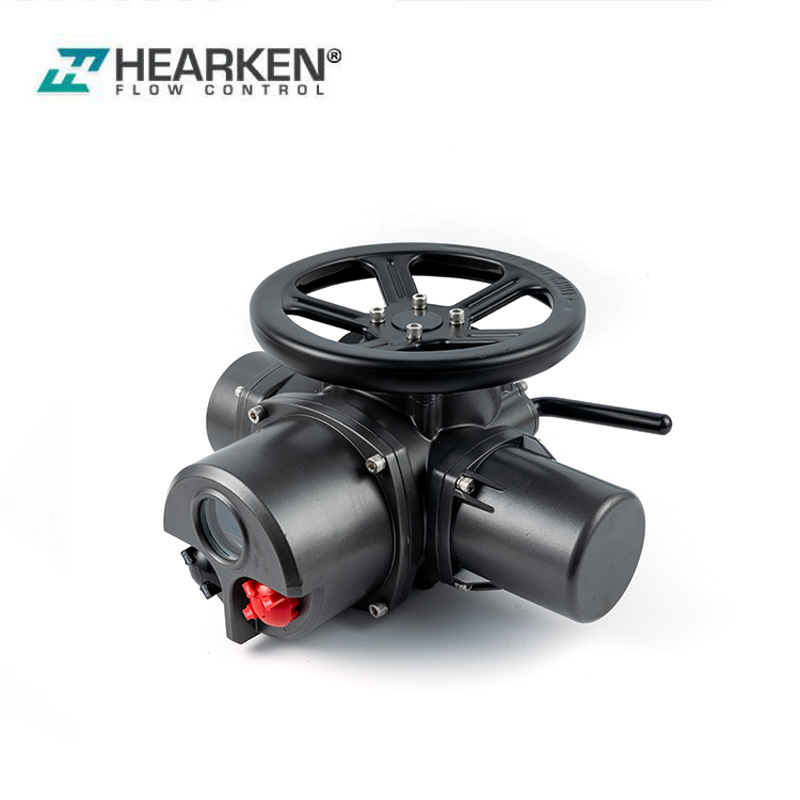
Why Does an Electric Actuator Overheat During Operation?
Learn how cycling, valve resistance, electrical conditions and the installa...

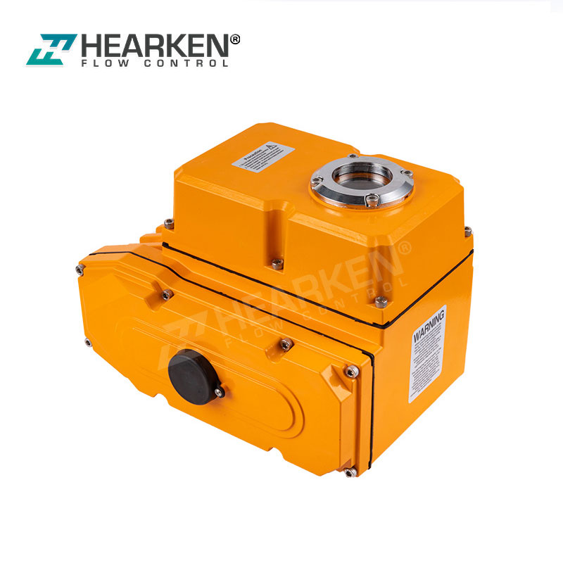


Torque & Design: 50 – 300 N·m (5~6 r/min) | Compact Die-Cast Aluminum Body (~10 kg) Control Modes: Standard On/Off | Optional Modulating (4–20mA / 0–10V / RS-485) Mounting Standards: ISO 5211 (F10 / F12) | JB/T 2920 Torque & GB/T 12222 Thrust Protection & Quality: IP67 Weatherproof | CE | SIL3 | 18-Month Warranty
HEA(M) Series Multi-Turn Electric Actuator is used for controlling 0~360-degree rotation valves and other similar products, such as butterfly valve, ball valve, damper, flapper valve, cock valve, etc. It is widely applied to petroleum, chemical, water treatment, shipping, paper, making, power plant, and other industries. Driven by 380V/220V/110VAC OR 24V/110VDC Power, Inputs 4~20mA or 0~10 VDC control signals, moves the valve to the right position, and achieves automatic control. The Maximum output torque is 300 N.m.
 |
 |
 |
|
Feature & Technical Spec |
Engineering & Buyer Advantage |
|
|
Certifications & 18-Month Factory Warranty Hearken Flow HEA(M) Series multi-turn electric valve actuators are manufactured in accordance with the ISO 9001:2008 standard. We have applied for CE certification, SIL 3 certification, RoHS compliance, and an IP67 protection rating, and come with an 18-month manufacturer’s warranty. |
International safety and quality certifications simplify the qualification review process for engineering bids and help you avoid import clearance delays for global distributors. |
|
|
Compact Design and Lightweight Enclosure All 50–300 N·m models use a high-strength die-cast aluminum alloy enclosure with a standard net weight of only about 10 kg. |
The lightweight design greatly reduces international air and sea freight costs, simplifies manual handling during installation, and reduces structural stress on the valve stem and piping. |
|
|
50–300 N·m Torque Output & Controlled Speed At a stable output speed of 5–6 r/min, the actuator provides rated output torques of 50 N·m (HEA005M), 100 N·m (HEA010M), 200 N·m (HEA020M), and 300 N·m (HEA030M). |
Hearken Flow HEA(M) multi-turn electric valve actuator provides enough seating and unseating torque for multi-turn valves while maintaining optimal operating speed to avoid water hammer in the pipeline. |
|
|
Dual Drive Standards (JB/T 2920 & GB/T 12222) We use F10/F12 flanges with ISO 5211 (PCD 102/125 mm); it supports direct installation of JB/T 2920 torque-type (non-stem-lifting, max. Φ28 mm) and GB/T 12222 thrust-type drive sleeves via standard adapter flange/sleeve kits, making it suitable for stem-lifting valves. |
Our HEA(M) Series multi-turn electric valve actuator can be installed directly and compactly on non-stem-lifting valves, while providing standardized adapter flanges and connection solutions for stem-lifting gate valves and globe valves, simplifying mounting for OEM valve manufacturers. |
|
|
Suitable Valve Size Range Standardized torque is suitable for gate valves (DN15–DN200), globe valves (DN15–DN100), and knife gate valves (DN50–DN250) across various pressure ratings (up to PN16). |
You can select the exact model required based on the specific specifications of each valve to avoid failures caused by insufficient torque while avoiding unnecessary costs resulting from oversized valves. |
|
|
360° Installation Flexibility IP67 weatherproof housing and symmetrical internal drive mechanism allow the actuator to be installed at any angle within a 360° range (vertical, horizontal, or angled). |
Hearken Flow offers maximum installation flexibility in tight pipeline spaces and confined industrial environments. |
|
|
Modular Control Architecture (On/Off & Modulating) Hearken Supply standard On/Off or fully integrated with the KZQ-10L smart modulating controller supporting 4–20 mA, 0–5 V, 0–10 V, and RS-485 Modbus RTU. |
You can source both standard on-off actuators and high-precision regulating actuators from a single factory, matching diverse project budgets and customer specifications. |
|
|
High-Precision PID Regulation & Adjustable Deadband The modulating multi-turn valve electric actuator uses advanced PID control algorithms with deadband sensitivity continuously adjustable from 0.1% to 3.0%. |
It can provide precise multi-turn valve position and stroke control across intermediate travel points while effectively suppressing motor hunting and reducing mechanical wear on gear trains. |
|
|
16-Fault Self-Diagnostics (Er0–Er15) & Fail-Safe Actions Integrated electronic protection includes 16 fault diagnostic codes (Er0 through Er15, corresponding to stalled rotor, phase loss, sensor failure, and overtemperature, respectively) and programmable fault-safe responses (fault hold, fault disconnect, and fault shutdown). |
Supports rapid on-site troubleshooting, provides remote alarm signals, and protects critical pipeline assets during unexpected signal loss or electrical failures. |
|
Problem |
Possible Cause |
How do we solve it? |
|
Power Indicator & LCD Screen Off |
• Power supply is not connected, or voltage is too low. • Incorrect incoming power wiring. • Internal power module or transformer damaged. |
We need to use a multimeter to verify incoming AC/DC voltage, check power terminals (L/N or U/V/W) against the wiring diagram, and replace the power board if incoming power is normal. |
|
Abnormal Indicator & Screen Display During Operation |
• LCD screen or LED indicator damaged. • Fault code actively triggered. • Main control circuit board fault. |
We need to inspect the digital display for specific error codes, verify supply voltage stability, and replace the display panel or main control circuit board if damaged. |
|
No Operation in Both Local & Remote Modes |
• Torque/limit switch wiring is open-circuit or tripped. • Motor thermal switch is open. • Controller locked in fault protection mode. • Motor drive circuit / solid-state relay failure. |
We need to check torque and thermal switch wiring continuity (terminals 18–20), power-cycle the HEA(M) series multi-turn electric valve actuator to clear fault locks, and inspect the motor drive circuit. |
|
Local Mode Operates, but Remote Control Fails |
• Actuator is not set to "Remote" mode. • Remote 4–20 mA signal is reversed, disconnected, or missing. • Position feedback potentiometer unmeshed or slipped. • Remote control parameter (iP) configured incorrectly. |
We press the “Switch” button to switch to remote mode, verify the polarity of the 4–20 mA loop, check the sensor gear meshing, and set the parameter to P=9.1 (iP=0 indicates modulation; iP=1 indicates on/off). |
|
Local Cannot Operate, but Remote Operates |
• Actuator is locked in Remote mode. • Local pushbuttons are stuck, worn, or not fully pressed. • Local pushbutton circuit board damaged. |
We press the “Switch” button to enter local mode, check the mechanical operation of the button, and test the continuity of the keyboard contacts. |
|
Operates in One Direction Only |
• Corresponding directional torque/limit switch wiring is open or faulty. • Actuator hit mechanical travel limit or over-torque stop. • Motor single-phase winding open, stalled, or wired incorrectly. • Drive circuit component damaged. |
We need to verify the continuity of the limit switches and torque switches, clear any mechanical obstructions from the valve seat and valve stem, measure the resistance of the motor windings, and inspect the drive circuit. |
|
Immediate Operation on Power-Up Without Control Signal |
• Wiring connection error. • Signal-loss fail-safe action triggered (set to Fail-Open or Fail-Close). • Unexpected control signal presence. • Configured for 2-wire control mode. |
We need to check the control terminal connections, verify the fail-safe behavior (hold/on/off) for parameter P=2.1 (I=0/1/2/3) in the event of a signal loss, and verify the status of the input signal. |
|
Operates at Intermediate Positions, Stops at Limits |
• Torque switch wiring reversed. • Valve disc/stem mechanically jammed upon reaching end limits. • Limit circuit wiring open. • Drive circuitry damaged. |
We need to check the wiring polarity of the limit switches and torque switches, verify the valve seats are properly aligned to avoid sticking at the end of the stroke, and check the continuity of the wiring. |
|
Action / Movement Direction Reversed |
• Motor phase/winding wiring reversed. • Zero/Span valve stroke calibration was performed in reverse. • Direct/Reverse action setting (Ac) is configured incorrectly. • Analog command signal polarity inverted. |
Adjust the phase sequence of the motor wiring, recalibrate the zero position and full-stroke limits, or adjust parameter P=2.1 (Ac=0 indicates forward action; Ac=1 indicates reverse action). |
|
No Output Current Feedback or Intermittent |
• Output 4–20 mA feedback loop wiring loose or disconnected. • Feedback potentiometer or encoder sensor damaged. • Analog feedback circuit board damaged. |
We need to check the feedback terminal connections (terminals 6 and 7), verify the signal loop continuity and load resistance (≤500 Ω), and test the sensor resistance linearity. |
|
Feedback Current Drift, Inaccurate or Static |
• Feedback potentiometer or encoder sensor faulty. • Output current calibration error. • Sensor drive gear slipping or improperly meshed with main shaft. • Circuit board fault. |
We need to tighten the sensor drive gear set, check the meshing between the gears and the main shaft, and recalibrate the output zero point (oL=4 mA) and range (oH=20 mA) via menu P=1.1. |
|
Problem |
Possible Cause |
How do we solve it? |
|
LCD displays Er0 (Power Phase Loss) |
380 V AC 3-phase incoming power is missing a phase, or the power terminals are loose. |
We need to inspect the incoming 380V AC 3-phase power lines using a multimeter to confirm phase balance and secure all wiring connections at the power terminals. |
|
LCD displays Er1 (Parameter Storage Error) |
The internal memory parameters have not yet been initialized, or the standard 4–20 mA input/output current calibration has not yet been performed. |
We need to go to parameter menu P=1.1 to calibrate the 4–20 mA output current (oL/oH), then go to menu P=11.1 to calibrate the 4–20 mA input current (iL/iH), and finally save the settings via P=5.0. |
|
LCD displays Er2 (Internal Over-Temperature) |
HEA(M) series multi-turn electric valve actuator internal operating temperature is higher than the safety limit (default 85°C) due to high ambient heat or higher than the duty cycle ratings. |
We need to stop the operation to allow the motor to cool down, verify that ambient ventilation complies with operating limits, and reduce the operating frequency to match the rated duty. |
|
LCD displays Er3 (Opening Stall Protection) |
When power is applied to the motor, the valve opens; however, due to mechanical binding, a seized valve stem, or gear slippage, the position sensor does not detect any change in the valve’s travel. |
We inspect the valve stem, packing gland, and actuator drive bush for mechanical binding or foreign debris, ensuring the valve disc rotates freely. |
|
LCD displays Er4 (Closing Stall Protection) |
The motor is energized to close, but the position sensor detects no valve stroke movement due to line blockage, high differential pressure, or tight packing. |
We need to check the valve stem, stuffing box, and actuator drive sleeve for mechanical binding or foreign objects, and keep the valve disc can rotate freely. |
|
LCD displays Er6 (Control Signal Loss / Too Low) |
The 4–20 mA command signal from the DCS/PLC is disconnected, the polarity is reversed, or the input loop current is below 3.0 mA. |
Check the loop wiring at input terminals 4 (+) and 5 (-), measure the signal current with a multimeter, and if the signal source has drifted, recalibrate the input zero-current (iL). |
|
LCD displays Er7 (Control Signal Over-Current) |
The input analog command signal exceeds 150% of the rated calibration standard due to an analog output card fault or wiring surge. |
We need to check the DCS/PLC analog output channel, verify signal loop resistance (<250Ω), and recalibrate the input range (iH) using a stable 20.00 mA signal. |
|
LCD displays EL (Limit / Torque Switch Reversed) |
At the terminal block, the wires for the torque open and torque close microswitches were reversed. |
We need to swap the torque open wire and the torque close wire on the internal terminal block. |
|
LCD displays Er9 (Signal Outside Electronic Limits) |
The received control signal indicates that the valve position has exceeded the preset electronic lower limit (cL) or upper limit (cH). |
Access parameter menu P=2.1 to check and reset the electronic travel limits (cL=0.0%, cH=100.0%) or recalibrate the range of the 4–20 mA control signal input. |
|
LCD displays Er10 (Stroke Span Too Small) |
The travel range between the zero (uL) and full (uH) calibration points is too narrow for reliable position sensing. |
We need to recalibrate the travel limits by driving the valve to the true mechanical 0% (uL) and 100% (uH) positions to keep the sensor with sufficient travel range across the entire travel range. |
|
LCD displays Er11 (Thermal Switch / Torque Common Disconnected) |
The external motor thermal protection switch has tripped, or the torque common wire (Terminal 18) is loose or disconnected. |
Test the continuity of the thermal protection switch circuit, and after the motor has cooled down, verify that the torque common wire at Terminal 18 is securely connected. |
|
LCD displays Er12 (Potentiometer / Encoder Sensor Fault) |
Position feedback sensor wires are loose, feedback drive gears are unmeshed/slipping, or the potentiometer is rotated into its dead zone. |
We need to inspect the feedback sensor wiring (terminals 24–28), ensure the gear between the potentiometer and the drive shaft is meshing properly, and adjust the potentiometer to the valid linear range (500 Ω–10 kΩ). |
|
LCD displays Er13 (Open Over-Torque Tripped) |
The HEA(M) series modulating actuator encountered excessive resistance during the opening process or triggered the opening torque limit switch or opening limit switch. |
We need to check the valve stem lubrication, packing friction, and pipeline pressure differential, and then verify the trip settings of the opening limit and torque switches. |
|
LCD displays Er14 (Close Over-Torque Tripped) |
The HEA(M) actuator encountered excessive resistance during the closing stroke or triggered the closing overtorsion or closing limit switch. |
Check the valve seat for solid debris or scale that may be preventing the valve disc from sealing completely, verify the alignment of the valve disc, and check the setting of the closing torque switch. |
|
LCD displays Er15 (Motor Rotation Direction Error) |
Due to the reversed phase sequence, the motor’s direction of rotation is opposite to the counting direction of the position feedback sensor. |
We swap any two phase wires of the motor (for example, the U and V terminals) to synchronize the motor’s rotation with the feedback sensor’s increments. |
HEA(M) series multi-turn electric valve actuators are designed with permanently lubricated gear trains and weatherproof enclosures, requiring minimal maintenance under standard operating conditions. Regular preventive inspections keep the actuator in continuous operation and extend valve life.
IP67 Weatherproof Protection: Inspect the cable entry conduit plugs and cable gland seals. Keep all unused conduit entries sealed with certified blind plugs to avoid moisture and condensation from entering the electrical compartment.
Cover O-Rings: Whenever the electrical cover is removed for inspection, verify the NBR O-ring seal is clean, free of cracks, and correctly seated in its groove before evenly tightening the cover screws.
Factory Lubrication: The internal worm gear and bearings are filled with high-quality synthetic grease during assembly and generally do not require periodic replenishment under standard operating conditions.
Stem Nut / Adapter Bushing (Rising-Stem Applications): For rising-stem gate and globe valves equipped with external thrust drive nuts/sleeves, apply lithium-based extreme pressure grease to the valve stem threads every 6 to 12 months to prevent stem binding and excessive friction.
Terminal Tightness: In environments where the pipeline is subject to continuous vibration, inspect the terminal screws (power, control, and feedback) once every 12 months to ensure the connections are secure.
Insulation Check: During plant maintenance, use a 500V DC megohmmeter to test the motor’s insulation resistance (acceptable value > 100 MΩ).
Internal Anti-Condensation: For equipment installed outdoors in high-humidity or coastal areas, keep the continuous power supply to the internal space heater or electronic circuit boards to prevent condensation.
Storage Conditions: Store the actuators in a dry, well-ventilated warehouse (ambient temperature: -20°C to +60°C; relative humidity: 90%). Keep the protective plastic caps on the terminals intact until installation.


|
Model Parameters |
HEA005M |
HEA010M |
HEA020M |
HEA030M |
|
AC/DC24、AC/DC110、AC/DC220V、AC/DC380V |
||||
|
Motor Power (KW) |
0.1 |
0.25 |
||
|
Torque (N.m) |
50 |
100 |
200 |
300 |
|
Output Speed (r/min) |
5 |
18/24 |
16 |
8 |
|
Available Control Circuit |
On-off (A 220V; W380V)、Intelligent Z; |
|||
|
Max. Stem Diameter(mm) |
20 |
28 |
||
|
Turning Cycles |
50 |
50 |
||
|
Weight (Kg) |
10 |
15 |
||
|
Withstand Voltage Class |
1500VAC / minute |
|||
|
Insulating Resistance |
100MΩ/500VDC |
|||
|
Protection Class |
IP67 |
|||
|
Ambient Temperature |
-28ºC~+60ºC (Other temperatures can be customized) |
|||
|
Installation Angle |
360°C at any angle |
|||
|
Shaft Body Material |
Aluminium alloy die-castings |
|||
|
DUTY |
Short 10 minutes (30 minutes for special order) |
|||
-series-multi-turn-electric-valve-actuatorswdkqvl.webp) Connection Dimension

|
Model |
Torque type JB2920 |
|||||||||||
|
Flange No. |
D |
D1 |
D2 |
h1 |
f |
h |
d1 |
d2 |
d |
n |
α |
|
|
HEA005M |
2I |
125 |
102 |
60 |
2 |
4 |
8 |
30 |
45 |
M10 |
4 |
45° |
|
HEA010M |
2 |
125 |
102 |
60 |
2 |
4 |
8 |
30 |
45 |
M10 |
4 |
45° |
|
HEA020M |
2I |
125 |
102 |
60 |
2 |
4 |
8 |
30 |
45 |
M10 |
4 |
45° |
|
HEA030M |
2 |
125 |
102 |
60 |
2 |
4 |
8 |
30 |
45 |
M10 |
4 |
45° |
|
Model |
Thrust type GB12222 |
|||||||||
|
Flange No. |
D |
D1 |
D2 (f8) |
f |
d1 max |
d |
L |
n |
α |
|
|
HEA005M |
F10 |
125 |
102 |
70 |
2 |
4 |
8 |
30 |
45 |
M10 |
|
HEA010M |
F10 |
125 |
102 |
70 |
2 |
4 |
8 |
30 |
45 |
M10 |
|
HEA020M |
F10 |
125 |
102 |
70 |
2 |
4 |
8 |
30 |
45 |
M10 |
|
HEA030M |
F10 |
125 |
102 |
70 |
2 |
4 |
8 |
30 |
45 |
M10 |
Please follow this five-step selection guide to select the exact HEA(M) actuator model for your gate valve, globe valve, or knife gate valve.
Sure the maximum operating torque of the valve at working pressure (including sealing/unsealing forces and packing friction), and apply the recommended safety factor (generally 20%–30% for clean liquid media; 30%–50% for slurries, high-viscosity, or high-temperature media). Based on the calculated torque, select the appropriate HEA(M) model:
|
Model |
Rated Torque |
Motor Power |
Output Speed |
Max Stem Dia. |
Mounting Flange |
|
HEA005M |
50 N·m |
0.09 kW |
5 r/min |
Φ20 mm |
ISO 5211 F10 / F12 |
|
HEA010M |
100 N·m |
0.12 kW |
5 r/min |
Φ28 mm |
ISO 5211 F10 / F12 |
|
HEA020M |
200 N·m |
0.16 kW |
5 r/min |
Φ28 mm |
ISO 5211 F10 / F12 |
|
HEA030M |
300 N·m |
0.18 kW |
6 r/min |
Φ28 mm |
ISO 5211 F10 / F12 |
Wedge / Slab Gate Valves: DN15 – DN250
Globe Valve: DN15 – DN100
Knife Gate Valves & Slurry Valves : DN50 – DN300
Damper Flap Valves & Cock Valves
Penstocks & Sluice Gates
The sizing charts below provide reference values only based on standard clean water at ambient temperature. The final actuator model must always be according to the valve's actual operating torque (taking into account differential pressure, media viscosity, solid slurry content, packing tightness, and a 20%–30% safety factor). The HEA(M) series covers rated torques up to 300 N·m (HEA030M); for valve requirements exceeding 300 N·m, please contact us at [email protected] for a larger heavy-duty actuator series.
|
Pressure (bar) / Bore |
DN15–40 |
DN50 |
DN65 |
DN80 |
DN100 |
DN125 |
DN150 |
DN200 |
DN250 |
|
PN 2.5 ~ 6 |
HEA005M |
HEA005M |
HEA005M |
HEA005M |
HEA010M |
HEA010M |
HEA015M* |
HEA015M* |
HEA020M |
|
PN 10 ~ 16 |
HEA005M |
HEA005M |
HEA005M |
HEA010M |
HEA015M* |
HEA015M* |
HEA020M |
HEA020M |
HEA020M |
|
PN 25 ~ 40 |
HEA005M |
HEA005M |
HEA010M |
HEA010M |
HEA015M* |
HEA020M |
HEA020M |
HEA030M |
HEA030M |
|
PN 64 ~ 100 |
HEA005M |
HEA005M |
HEA010M |
HEA010M |
HEA015M* |
HEA020M |
HEA030M |
/ |
/ |
|
Pressure (bar) / Bore |
DN15–40 |
DN50 |
DN65 |
DN80 |
DN100 |
DN125 |
DN150 |
DN200 |
DN250 |
|
PN 10 ~ 16 |
HEA005M |
HEA005M |
HEA005M |
HEA010M |
HEA015M* |
HEA020M |
HEA030M |
/ |
/ |
|
PN 25 ~ 40 |
HEA005M |
HEA005M |
HEA010M |
HEA010M |
HEA020M |
HEA020M |
HEA030M |
/ |
/ |
|
PN 64 ~ 100 |
HEA005M |
HEA005M |
HEA010M |
HEA010M |
HEA020M |
HEA030M |
/ |
/ |
/ |
|
Valve Size |
DN50 |
DN65 |
DN80 |
DN100 |
DN125 |
DN150 |
DN200 |
DN250 |
DN300 |
|
Recommended Model |
HEA010M |
HEA010M |
HEA010M |
HEA010M |
HEA010M |
HEA015M* |
HEA020M |
HEA020M |
HEA020M |
(Models marked with * represent larger torque configurations available on request)
Stem Diameter Check: Ensure the outer diameter of the valve stem does not exceed the drive bore diameter of the actuator (Φ20 mm for HEA005M; Φ28 mm for HEA010M–HEA030M).
Mechanical Drive Interface:
Torque Type (JB/T 2920): Suitable for non-rising-stem valves; uses direct mounting the ISO 5211 F10/F12 standard; the internal valve stem nut in this type of valve bears the axial thrust.
Thrust Type (GB/T 12222): Suitable for rising-stem gate valves and globe valves; uses an external adapter flange and drive nut assembly to provide the space required for the valve stem’s linear travel.
Control Mode Selection:
Standard On/Off Type: Driven by an external power supply or switch signal with passive dry-contact limit switch feedback to achieve isolation in the fully open or fully closed states.
Intelligent Modulating Type (KZQ-10L Module): Comes with a microprocessor control board, supporting 4–20 mA / 0–10 V / 0–5 V proportional control, LCD display, automatic stroke calibration, and RS-485 Modbus RTU communication.
Operating Voltage Selection:
AC 220V (Single Phase)
AC 110V (Single Phase)
AC 380V (3-Phase)
AC/DC 24V
Q1: What are the rated operating currents for 220V AC and 380V AC models?
A: Below is the standard rated current table for the HEA(M) series across all torque ratings:
|
Model |
Rated Torque |
Rated Current (220V AC) |
Rated Current (380V AC) |
|
HEA005M |
50 N·m |
0.8 A |
0.48 A |
|
HEA010M |
100 N·m |
1.0 A |
0.80 A |
|
HEA020M |
200 N·m |
1.5 A |
1.00 A |
|
HEA030M |
300 N·m |
1.8 A |
1.20 A |
Note: Because the motor starts smoothly, the inrush current is generally close to the rated current (for example, approximately 1.0 A for the HEA010M 220V model).
Q2: Can you supply 415V AC 3-phase power, and is there an extra cost compared to 380V?
A: Yes. In addition to the standard 380V AC 3-phase HEA(M) series multi-turn electric valve actuator, we supply 415V AC 3-phase. 415V AC models share the same pricing as standard 220V/380V actuators. Single-phase 110V AC and 24V AC/DC are also available upon request.
Q3: Do the actuator motors include built-in thermal overload protection?
A: Yes. All HEA(M) series electric valve actuators are equipped with a built-in motor thermal protection switch. When the internal temperature of the motor exceeds safe operating limits, the thermal protection switch automatically cuts off the power supply to prevent the windings from burning out.
Q4: Can we switch between “on/off” and “modulating” control modes?
A: This depends on the model originally purchased:
Converting the “on/off” model to a “modulating” model: We do not recommend performing this modification yourself. The internal terminal block and power lines of the HEA(M) multi-turn actuator are soldered in place during assembly, and the internal circuits of the standard on/off and modulating models are fundamentally different. To ensure the integrity of the IP67 protection rating and the reliability of electrical isolation, we recommend ordering a modulating actuator directly from us.
Using a “modulating type” model (equipped with a KZQ-10L module) as a “switch-type” actuator: Yes, absolutely. Our KZQ-10L smart controller uses a native dual-mode architecture. If you purchased a modulating type model, you can freely switch between “proportional control” and “standard switch operation” in the LCD parameter menu without modifying any internal hardware:
Modulating Mode (4–20 mA / 0–10 V): Enter parameter menu P=9.1 and set iP = 0 for proportional positioning.
Standard On/Off Mode (Dry Contact / Switch Signals): Enter parameter menu P=9.1 and set iP = 1 to operate as a standard cut-off unit responding to remote Open / Close / Stop commands.
Q5: Can the cycle of operating turns/travel stroke be adjusted in the field (e.g., changing from 10 turns to 4 turns, or single-turn full stroke)?
A: Yes. You can easily adjust the travel stroke:
Modulating Type (KZQ-10L): Travel limits and turns can be recalibrated on the LCD screen menu (uL for zero and uH for span) without opening the electrical enclosure.
Standard On/Off Type: The internal mechanical limit cams can be loosened and repositioned to set any cycle, from 1 turn to full stroke.
Q6: What is the output rotation speed? Can it be customized to run faster?
A: The standard output speed is 5 r/min (5 r/min for models HEA005M–020M and 6 r/min for model HEA030M). This speed has been precisely engineered to balance high output torque with stable valve operation, thereby preventing valve line surges and water hammer when the valve closes fully.
Q7: Does the HEA(M) actuator have an automatic spring-return fail-safe function in the event of a power failure?
A: No. Our HEA(M) Series Multi-turn electric actuators use a self-locking worm gear drive mechanism that mechanically holds the valve in its final position during a power failure. For proportional control models, when the main power supply remains connected, but the control signal is lost (e.g., a 4–20 mA signal interruption), electronic fail-safe operation is supported (maintain current position, fail-open, or fail-close).
Q8: Can the actuator be connected to external time relays, cycle counters, or automated timing control boxes?
A: Yes. The standard HEA(M) actuator supports external passive contact (dry contact) commands and provides passive on/off position feedback signals. Therefore, it is fully compatible with external cycle timers, PLC sequence controllers, interval relays, and digital stroke counters, enabling automatic cyclic operation.
Q9: What are the dimensions of the bottom mounting flange? If our valve connection dimensions are different, can the mounting interface be customized?
A: Standard dimensions: All HEA(M) actuator models use standardized ISO 5211 F10 / F12 bottom-mount flanges (PCD 102 mm with 4×M10 bolt holes, PCD 125 mm with 4×M12 bolt holes). Our actuators come with these two bolt hole patterns (including threads) pre-machined, allowing for direct bolt-on installation to compatible valves.
Custom adaptation solutions for different sizes: If your valve has different connection dimensions (e.g., ISO 5211 F14, DIN/ANSI standards, non-standard bolt hole patterns, or specific stem shapes), we can custom-machine adapter flanges (mounting plates) and dedicated drive couplings/stems based on your valve drawings.
Q10: How should the HEA(M) be installed on rising-stem and non-rising-stem valves?
A: Non-Rising Stem Valves: For valves with a stem diameter of no more than Φ28 mm, the actuator can be directly mounted on the drive sleeve of the actuator using a standard JB/T 2920 torque-type interface.
Rising-Stem Valves: Due to limited internal height in HEA(M) series compact multi-turn electric valve actuators, stem-exposed gate valves and globe valves must be connected via an external adapter flange and drive nut assembly (GB/T 12222 thrust type) to allow for the linear movement of the valve stem.
Q11: Do the actuators come with a brand nameplate or label? Do you offer OEM private labeling services?
A: We provide 3 flexible branding options to support your distribution channel and business model:
Hearken Flow Brand: The actuator can be supplied with our "Hearken Flow" nameplates, certification badges, and standard factory documentation.
Neutral / Unbranded: Actuators ship without any brand markings, equipped only with a neutral technical nameplate (indicating model specifications, voltage, and torque parameters) and a neutral wiring diagram—ideal for distributors and resellers.
Custom OEM/Private Label: We offer private labeling services. This includes laser-etching your company’s logo, custom model numbers, company contact information, serial numbers/barcodes, and on-demand custom powder-coated housing colors (e.g., industrial blue, orange, yellow, or gray).
Q12: What is your warranty policy, and what certifications do you have?
A: All HEA(M) series multi-turn electric valve actuators come with an 18-month manufacturer’s warranty effective from the date of shipment. Our HEA(M) series is manufactured in accordance with the ISO 9001:2008 quality management system and has undergone testing for CE certification, SIL3 functional safety certification, and IP67 protection rating.
2026
/
Learn how cycling, valve resistance, electrical conditions and the installa...

2026
/
Check mounting, air supply, valve travel and position feedback before putti...
2026
/
Learn why pneumatic actuators lose air pressure, where leaks occur, and wha...
2026
/
Industrial automation relies on precise motion control to regulate the flow...
GET A QUOTE