
 English
 Español
 Português
 Pусский


Why Does an Electric Actuator Overheat During Operation?
Learn how cycling, valve resistance, electrical conditions and the installa...

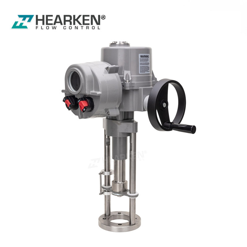


Thrust & Stroke: 1.5 kN to 50 kN thrust | 25 mm to 100 mm linear stroke Control Options: On-Off, 4-20mA / 0-10V Modulating, Smart Integrated (ICM) Protection Rating: IP67/IP68 Weatherproof & Exd IIC T6 Explosion-Proof Certifications: ISO 9001, CE, SIL3, ATEX
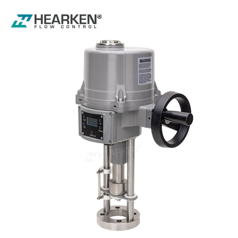
Hearken Flow HUS Series is a rugged, high-precision electric linear actuator designed for precise modulating and on-off control of globe valves, control valves, and dampers. We provide a thrust range of 1.5 kN to 50 kN. Our HUS series electric linear valve actuator
comes standard with IP67 protection and is available with an optional explosion-proof enclosure. You can calibrate all settings using an infrared remote without opening the cover. Built for OEM valve mounting and distributor stocking.
 |
 |
 |
 |
 |
|
Feature & Technical Spec |
Engineering & Buyer Advantage |
|
|
Certifications & Compliance Hearken Flow HUS Series electric linear valve actuators have applied for SIL3 Certificate, ATEX Certificate, CE Certification, Explosion-proof Exd IIC T6Gb Certificate, IP67 Weatherproof, etc |
International safety certifications simplify technical audits for project tenders and avoid customs clearance delays during import. |
|
|
Wide Thrust Output & Flexible OEM Mounting The thrust output range is 1.5 kN to 50 kN, with a linear stroke of 25 mm to 100 mm. Mounting dimensions, center distances, and mounting brackets can all be customized to round, square, or threaded rod connections (M8 to M20 thread depths). |
Hearken Flow HUS series electric linear actuator can be mounted directly onto globe, control, and diaphragm valves without extra stem machining |
|
|
Non-Intrusive Infrared Setup & Absolute Encoder Our HUS series intelligent linear electric actuator is equipped with an LCD, an infrared remote control, and an external knob for parameter settings; it features an integrated single-turn absolute encoder for precise position feedback. |
We can calibrate the travel limits and the 4–20 mA signal without opening the housing, thereby keeping moisture and dust out and ensuring that the valve position is retained in the event of a power failure. |
|
|
Clutchless Emergency Manual Override System Hearken Flow uses an internal endless screw drive design that requires no manual clutch lever. Equipped with push-handles, spanner drives, or direct handwheels depending on actuator frame size. |
In the event of a power outage, our actuators allow the handwheel to be turned directly without the need to operate the clutch lever, avoiding manual operation from becoming stuck or creating operational hazards. |
|
|
Protected Induction Motor & Smart Circuitry Hearken Flow HUS Series heavy-duty electric linear actuators use Class E/F-insulated induction motors and are equipped with low rotational inertia, thermal overload protection, motor stall protection, and instantaneous reverse delay; the 380V models also include automatic phase sequence correction. |
Our actuator can avoid motor, gear, and valve stem damage caused by torque spikes, sudden reverse commands, or phase wiring errors, drastically reducing warranty claims. |
|
|
Comprehensive Passive Contact Feedback & Signal Output We provide passive contact outputs for FULL OPEN, FULL CLOSE, FAULT, and REMOTE/LOCAL status, alongside 4-20mA transmitter output feedback. |
Hearken Flow HUS series electric linear valve actuator supports seamless integration with DCS/PLC control systems to enable real-time remote monitoring and immediate fault notifications in the central control room. |
|
|
Anti-Condensation Heater & High-Temp Adaptation Our HUS series electric linear actuators feature an internal space heater designed to balance temperature differences and avoid condensation. In addition, medium-temperature (+100°C to +180°C) and high-temperature (> +180°C) mounting brackets are available as optional accessories. |
Protects internal electronic components in damp or cold outdoor environments and isolates the actuator body from high-temperature steam or fluid media. |
|
|
Global Power Voltage & Control Signal Flexibility Hearken Flow HUS Series electric linear actuators support 24 VDC, 110 VAC, 220 VAC, and three-phase 380 V/440 V power supplies. Control signal options include switch-type (On/Off), 4–20 mA, 0–5 V, 2–10 V, and intelligent ICM integrated control. |
We are able to simplify system integration across global projects by accommodating various power supply standards and control signal protocols without requiring custom electrical redesigns. |
|
|
Powder-Coated Aluminum Shell & Vibration Resistance We used anodized aluminum alloy and polyester powder coating. Tested to withstand 10g vibration levels across XYZ axes (0.2–34 Hz, 30-minute duration) |
Our enclosure can avoid shell corrosion in harsh outdoor or chemical environments while protecting internal components from severe pipeline vibration. |
|
Performance features |
Description |
Performance features |
Description |
|
Shell |
The shell is made of anodized aluminum alloy and coated with polyester powder. |
Limiter |
Power cut-off + passive feedback (Vmax 250V,Imax5A) |
|
Protection Grade |
IP 67、Exd IIC T6Gb(TBD)、Ex tb IIIC T80°CDb(TBD) |
Pointer dial |
For valve position indication, it will rotate with the valve |
|
Motor |
Totally enclosed cage induction motor, Low rotational inertia, insulation class F, built-in overheat protection. |
Heater |
Used to balance temperature difference and prevent condensation. Ensure that the internal electrical components work normally(Optional) |
|
Hand wheel& endless screw |
After a power failure, the hand wheel can be used for manual control. Internal endless screw design, no clutch. Light and easy to control |
Temperature resistance |
ON/OFF Types: -20°C~+60°C( -4°F~140°F) Modulating Types: -20°C~+55°C( -4°F~131°F) |
|
Mounting base |
ISO 5211 Design, high versatility; the transmission shaft adopts a spline shaft design. |
Humidity resistance |
Maximum relative humidity 90% (non-condensing) |
|
Limit Configuration |
Mechanical Limiter + Electrical Limiter |
Seismic capacity |
XYZ10g.0.2~34Hz, 30mins |
Hearken Flow offers two electric linear actuator platforms to match different valve automation requirements and project budgets:
HUS Series: A heavy-duty, certified industrial linear actuator equipped with a squirrel-cage induction motor and a clutchless worm gear drive, up to 50 kN of thrust; it features an Exd IIC T6Gb explosion-proof rating and supports non-intrusive infrared remote calibration.
HUBL Series: A compact and cost-effective linear actuator driven by a brushless DC (BLDC) motor with an integrated digital display and 4–20 mA modulating control (M1) functionality. It is specifically designed for standard valve automation applications in non-hazardous environments, such as HVAC, water treatment, and light industry.
|
Specification |
HUS Series (Heavy-Duty / Hazardous) |
HUBL (Compact / Cost-Effective) |
|
Thrust Output |
1.5 kN to 50 kN |
1 kN to 30 kN |
|
Stroke Range |
25 mm to 100 mm |
30 mm to 100 mm |
|
Motor Type |
Cage induction motor (Class E/F) |
Brushless DC (BLDC) motor |
|
Drive & Gearing |
Self-locking endless screw (no clutch required) |
Spur & planetary gearing with pull-out clutch |
|
Manual Override |
Clutchless direct drive (handwheel / push handwheel/spanner) |
Pull-out clutch handwheel |
|
Display & Setup |
Non-intrusive infrared remote + external knobs + 128x64 LCD |
Onboard digital display with 4 push buttons (requires cover removal) |
|
Control Signal |
On/Off, 4–20 mA (M1), 0–5V, 2–10V, or Intelligent ICM |
4–20 mA Modulating (M1), 0–5V, 2–10V |
|
Enclosure Rating |
IP67 standard (optional IP68 submersible) |
IP65 standard |
|
Hazardous Area |
Exd IIC T6Gb Explosion-Proof available |
Non-explosion proof (general safe areas only) |
|
3-Phase Power |
380V / 440V (with automatic phase sequence correction on ICM) |
380V (standard phase wiring) |
Select the HUS Series if the following conditions apply:
Hazardous Environments: Suitable for areas with flammable gases or dust, requiring Exd IIC T6Gb explosion-proof certification.
High thrust requirements: Valve shut-off thrust exceeding 30 kN (up to 50 kN).
Non-invasive setup: External infrared remote calibration can be performed without opening the enclosure in damp or outdoor environments.
Clutchless Emergency Override: During a power failure, you can use the handwheel directly without having to engage the clutch lever.
Select the HUBL Series if the following conditions apply:
Non-hazardous safety zones: Installed in standard commercial HVAC, water treatment, or light industrial facilities where an explosion-proof enclosure is not required.
Compact Spaces and Low Thrust: Operating thrust requirements range from 1 kN to 30 kN, and piping installation space is limited.
Budget-Sensitive Projects: Seeking a cost-effective linear actuator that features an integrated digital display and 4–20 mA control capabilities.
We know that 90% of on-site actuator issues stem from initial stroke miscalibration, wiring mismatches, or environmental exposure during setup. Here is how we analyze and resolve the 10 most common scenarios for the HUS Series electric linear valve actuator and outline essential routine maintenance guidelines to keep the HUS Series electric linear valve actuator operating reliably.
|
Problem |
Possible Cause |
How do we solve it? |
|
Valve fails to seat properly & motor hums/trips over-torque |
The mechanical stroke was not “taught” to match the valve seat, causing the HUS series electric linear actuator to operate beyond its physical limits. |
We use the infrared remote in STOP mode to enter the Debug Menu. We operate the valve to true mechanical shutoff and calibrate "Close Position" to store the resistance as 0% reference. |
|
LCD Loss SIG (Signal Loss) warning |
Due to loose connections, open circuits, or reversed polarity at terminals 4 and 5 (or 10 and 11), the control card is not receiving the 4–20 mA current from the DCS/PLC. |
We use the multimeter to check the 4–20 mA current between the terminals and verify the polarity. Once the wiring is corrected, the alarm will clear automatically. |
|
4–20 mA input percentage mismatch (e.g., 4 mA reads 2.3% instead of 0%) |
Signal generator or DCS analog output card may have slight current drift or impedance deviation. |
We send the 4 mA from DCS, enter the Signal Calibration menu, and run "Low Control Calibration". Then send 20 mA and run "High Control Calibration" to synchronize. |
|
Control room receives inaccurate 4–20 mA position feedback |
Onboard 4–20 mA position transmitter output needs zero/span calibration to match the PLC input impedance. |
We connect the multimeter in series to the OUT terminals (8 and 9). During signal calibration, we use the remote “Up/Down” (UP/DO) keys to fine-tune the “Low/High Reverse” parameter until the multimeter readings exactly display 4.00 mA and 20.00 mA. |
|
Potentiometer gear slipping / resistance reaching hardware limits (< 100 or > 950) |
The calibration position for the travel limit is too close to the internal potentiometer's physical stop limit. |
The HUS series electric linear actuator's potentiometer is designed to operate within a range of 150 (closed position) to 850 (open position). If the value approaches either limit, the system will move the valve to the middle position and recalibrate the stroke to keep the gear within the optimal mechanical operating range. |
|
Actuator operates in reverse of DCS control command |
The control card's operating mode is reversed, or the phase sequence of the three-phase AC 380 V power supply wiring is reversed. |
The three-phase AC380V models feature automatic phase sequence correction; for single-phase or DC models, the “Forward/Reverse Operation” setting must be switched in the Debug menu. |
|
Actuator is unresponsive to remote DCS signals |
After installation and commissioning are complete, the local selection switch on the enclosure remains in “STOP” or “LOCAL” mode. |
We turn the red external selection knob on the enclosure to “REMOTE” mode. The LCD confirms it has entered remote mode and immediately responds to the DCS current-loop signal. |
|
Passive dry contact feedback (FULL OPEN / CLOSE) fails to signal PLC |
The actuator has not reached its precisely calibrated travel end limits (0.0% / 100.0%), or the contact wires are loose. |
We use the multimeter to test continuity between terminals 17 and 18 (SHUT) or 15 and 16 (OPEN). When the precise end limit is reached, the passive contacts close automatically. |
|
Arrival inspection: Verifying power integrity before initial power-on |
We worry about short circuits caused by rough shipping or internal harness damage. |
Before powering on the actuator, we use the multimeter to measure the resistance between the power input ports. If the HUS series electric linear actuator is in good condition, the reading should indicate infinity (OL), thereby ruling out the risk of a short circuit. |
|
Preventing internal condensation in humid/cold outdoor installations |
Maybe the enclosure cover is left on during humid weather, trapping ambient moisture inside. |
We keep the internal heater connected and never open the enclosure. All travel and signal settings are configured externally using the infrared remote control to keep the IP67 seal intact. |
We advise these basic checks during regular visits:
Travel Limit Calibration: After installing the HUS Series electric linear valve actuator on a new valve, use the infrared remote control to perform a non-intrusive recalibration to synchronize the zero and full-stroke positions.
LCD Window Cleaning: Remove dust and grease from the display window to ensure the infrared remote sensor has a clear line of sight for parameter configuration.
Keep the Internal Heater Powered On: When installing outdoors or in humid environments, keep the internal heater powered on at all times to avoid condensation from forming inside the enclosure.
Valve Stem Connection and Bracket Inspection: During routine valve maintenance, inspect the external mounting brackets and valve stem connection components, and apply grease to exposed threads to ensure smooth linear valve stem movement.
Check the Enclosure Seal: Inspect the cable gland and ensure the hex screws on the main cover are fully tightened to maintain the IP67 protection rating.


|
Model |
Thrust(KN) |
Speed(MM/S) |
Motor Power(W) |
Maximum stroke(MM) |
Insulation level |
Rated current(A) DC24V |
Rated current(A) AC110V |
Rated current(A) AC220V |
Rated current(A) AC380V |
Rated current(A) AC440V |
Weight(Kg) |
Manual Device |
|
HUS1S |
1.5 |
1 |
15 |
25 |
E |
1.2 |
0.4 |
0.3 |
/ |
/ |
2.8 |
Spanner |
|
HUS2S |
4 |
0.75 |
25 |
35 |
F |
2.1 |
0.51 |
0.26 |
0.26 |
0.21 |
8 |
Spanner |
|
HUS2S |
6 |
0.75 |
40 |
35 |
F |
3.5 |
0.73 |
0.33 |
0.26 |
0.21 |
8 |
Spanner |
|
HUS3S |
10 |
1 |
90 |
50 |
F |
6.8 |
1.7 |
0.8 |
0.9 |
0.7 |
8 |
Spanner |
|
HUS3S |
15 |
1 |
120 |
50 |
F |
8.5 |
2 |
1.1 |
0.9 |
0.7 |
8 |
Spanner |
|
Model |
Thrust(KN) |
Speed(MM/S) |
Motor Power(W) |
Maximum stroke(MM) |
Insulation level |
Rated current(A) DC24V |
Rated current(A) AC110V |
Rated current(A) AC220V |
Rated current(A) AC380V |
Rated current(A) AC440V |
Weight(Kg) |
Manual Device |
|
HUS1H |
1.5 |
1 |
15 |
25 |
F |
1.6 |
0.8 |
0.4 |
0.2 |
/ |
3.2 |
Push Hand Wheel Operation |
|
HUS2H |
4 |
0.75 |
25 |
35 |
F |
2.1 |
0.51 |
0.26 |
0.26 |
0.21 |
11 |
Push Hand Wheel Operation |
|
HUS2H |
6 |
0.75 |
40 |
35 |
F |
3.5 |
0.73 |
0.33 |
0.26 |
0.21 |
11 |
Push Hand Wheel Operation |
|
Model |
Thrust(KN) |
Speed(MM/S) |
Motor Power(W) |
Maximum stroke(MM) |
Insulation level |
Rated current(A) DC24V |
Rated current(A) AC110V |
Rated current(A) AC220V |
Rated current(A) AC380V |
Rated current(A) AC440V |
Weight(Kg) |
Manual Device |
|
HUS2 |
4 |
0.5 |
25 |
35 |
F |
1.8 |
1 |
0.45 |
0.3 |
0.25 |
12 |
Clutchless Hand Wheel |
|
HUS2 |
6 |
0.5 |
40 |
35 |
F |
3.5 |
0.73 |
0.33 |
0.26 |
0.21 |
12 |
Clutchless Hand Wheel |
|
HUS3 |
10 |
0.5 |
90 |
50 |
F |
6.8 |
1.7 |
0.8 |
0.9 |
0.7 |
14 |
Clutchless Hand Wheel |
|
HUS3 |
15 |
0.5 |
120 |
50 |
F |
8.5 |
2 |
1.1 |
0.9 |
0.7 |
14 |
Clutchless Hand Wheel |
|
HUS4 |
25 |
0.65 |
200 |
80 |
F |
/ |
4.8 |
2.8 |
1.2 |
1.1 |
22 |
Clutchless Hand Wheel |
|
HUS5 |
50 |
0.65 |
300 |
100 |
F |
/ |
7.7 |
5.1 |
1.9 |
1.8 |
50 |
Clutchless Hand Wheel |


Follow our 4-step purchase guide below to calculate the valve requirements, select compatible control features, and build a complete ordering code:
Please select the HUS series electric linear actuator frame size based on the valve’s required mechanical stroke and the calculated shut-off thrust:
Confirm the linear stroke (mm): The stroke length depends on the valve body size and the internal components (for example, DN25–DN50 control valves usually require a stroke of 25–30 mm, while DN80–DN150 control valves require a stroke of 50–100 mm).
Calculate the required thrust (kN): Calculate the thrust based on the maximum operating pressure differential (∆P), the seat area, the stem packing friction force, and the specified safety margin (usually +20% to +30%):
Required thrust = (seat area × ∆P) + stem packing friction force + safety margin
Match to HUS Series Electric Linear Actuator Frame Size Code (T):
HUS1S / HUS1H (1.5 kN Thrust): 25–30 mm stroke for small-bore or low differential-pressure valves.
HUS2S / HUS2H / HUS2 (4 kN / 6 kN Thrust): 25–50 mm stroke for medium-bore globe and control valves.
HUS3SL/ HUS3 (10 kN / 15 kN Thrust): 50–100 mm stroke for main process control applications.
HUS4 (25 kN Thrust): Up to 100 mm stroke for high differential-pressure service.
HUS5 (50 kN Thrust): Up to 100 mm stroke for large-bore or severe-service control valves.
Choose the control Mode based on your plant’s DCS/PLC automation:
For Simple Isolation / Shut-off Valves: Select O (Open/Close) for basic limit-switch On/Off control.
For Standard Proportional Flow Control:
Select M1 (4–20 mA) for industry-standard analog current loop control.
Select M2 (0–5 V) or M3 (2–10 V) for voltage-based PLC output loops.
For High-Spec, Non-Intrusive & Critical Process Loops: Select ICM (Intelligent Integrated Control) for installations requiring non-intrusive infrared remote setup (no cover opening), absolute position memory during power outages, local LCD indication, and passive contact feedback (Open, Close, Fault, Remote).
Voltage selection is based on available power supply and electrical safety standards:
Single-Phase AC Power (Standard Industrial Instrument Supply): Select D (220 VAC) or E (110 VAC) for standard control cabinet power.
Low-Voltage DC Power (Battery Backup or Solar Field Sites): Select F (24 VDC) for low-voltage safety loops or remote off-grid skids.
3-Phase AC Power (High Thrust / Heavy Duty Motors): Select I (380 VAC) or J (440 VAC 3Ø) for heavy-duty 3-phase installations. (Note: 380V models equipped with ICM include automatic phase sequence correction to avoid reverse rotation).
Protection options, enclosure ratings, and mounting accessories are selected according to hazardous area classification, ambient operating conditions, and valve stem:
Hazardous Area Certification & Enclosure Protection: For environments containing hazardous gases or dust, specify the Exd IIC T6 Gb explosion-proof rating. For non-hazardous outdoor locations, the standard protection rating is IP67.
Outdoor, High-Humidity, or Tropical Coastal Installations Environments: Specify the X option (built-in space heater) to balance temperature fluctuations and remove internal moisture condensation.
High-Temperature Process Fluids (> +100°C to +180°C or > +180°C): Specify the Extended Yoke or High-Temperature Bracket option to provide thermal isolation and avoid heat transfer from steam or high-temperature media to the HUS series electric linear actuator’s enclosure and electronic components.
Non-Standard Stem Threads or Yoke Mounting: Custom-machined yokes are available based on stem thread sizes (M8 to M20), stem shapes (round, square, or threaded), and center-to-center distance measurements.
|
Model |
Thrust (T) |
Available Control Methods (K) |
Supported Voltages (V) |
Optional Features (B) |
|
HUS1SL |
1.5 kN |
M1, M2, M3, O |
D, E, F |
Exd Explosion-Proof, X (Heater), Custom Color / Yoke |
|
HUS2SL |
4 kN / 6 kN |
M1, M2, M3, ICM, O |
D, E, F, I, J |
Exd Explosion-Proof, X (Heater), Custom Color / Yoke |
|
HUS3SL |
10 kN / 15 kN |
M1, M2, M3, ICM, O |
D, E, F, I, J |
Exd Explosion-Proof, X (Heater), Custom Color / Yoke |
|
HUS1HL |
1.5 kN |
M1, M2, M3, ICM, O |
D, E, F |
Exd Explosion-Proof, X (Heater), Custom Color / Yoke |
|
HUS2HL |
4 kN / 6 kN |
M1, M2, M3, ICM, O |
D, E, F, I, J |
Exd Explosion-Proof, X (Heater), Custom Color / Yoke |
|
HUS2L |
4 kN / 6 kN |
M1, M2, M3, ICM, O |
D, E, F, I, J |
Exd Explosion-Proof, X (Heater), Custom Color / Yoke |
|
HUS3L |
10 kN / 15 kN |
M1, M2, M3, ICM, O |
D, E, F, I, J |
Exd Explosion-Proof, X (Heater), Custom Color / Yoke |
|
HUS4L |
25 kN |
M1, M2, M3, ICM, O |
D, E, I, J |
Exd Explosion-Proof, X (Heater), Custom Color / Yoke |
|
HUS5L |
50 kN |
M1, M2, M3, ICM, O |
D, E, I, J |
Exd Explosion-Proof, X (Heater), Custom Color / Yoke |
Example Ordering Code: HUS-HUS3-ICM-D-X
(Specifies a HUS Series Linear Actuator with 10–15 kN Thrust, Intelligent ICM Control, 220 VAC Power, and Built-in Anti-Condensation Space Heater).
Q1: Can HUS Series electric linear actuators be mounted directly onto globe valves, control valves, and diaphragm valves?
A: Yes. The HUS Series electric linear actuators feature customizable mounting dimensions, center distances, and stem connections designed for direct installation on globe valves, process control valves, and diaphragm valves. The stem connection options support round, square, or threaded stems (M8 to M20 thread sizes) without requiring extra stem machining.
Q2: How do you calibrate the travel limits and the 4–20 mA signal in hazardous or damp environments?
A: Calibration is completely non-intrusive. Equipped with an LCD, an infrared remote control, and external selector knobs, you can adjust stroke limits, zero/span settings, and 4–20 mA input/output parameters externally without opening the enclosure cover. This design effectively avoids moisture, dust, and explosive gases from entering the device.
Q3: Does the HUS actuator lose its calibrated valve position memory during a power failure?
A: No. The intelligent HUS (ICM) models use the integrated single-turn absolute encoder for position detection. During the power outage, position data is retained both mechanically and electronically; there is no need to replace the battery or manually recalibrate the position after power is restored.
Q4: How does the emergency manual override operate during the power outage?
A: The HUS series features the internal endless screw drive mechanism and does not require a manual clutch lever. You can turn the handwheel, push-handle, or spanner drive directly during the power loss without operating a clutch mechanism, removing the risk of manual operation jamming or lever kickback.
Q5: How do HUS actuators handle high-temperature process fluid media?
A: While standard mounting brackets are suitable for fluids with temperatures below +65°C, optional extended mounting brackets (yoke brackets) and high-temperature brackets are available for process fluid temperatures ranging from +100°C to +180°C and above +180°C. These brackets act as thermal barriers, avoiding heat from steam or high-temperature media from being conducted to the actuator enclosure and electronic modules.
Q6: How does the HUS actuator handle 3-phase (380V / 440V) power wiring and phase sequence protection?
A: For Intelligent Control Module (ICM) models: The intelligent control module features automatic phase sequence correction. If the phase sequence of the three-phase wiring (A/B/C) is reversed during installation, the intelligent control board will automatically adjust the phase sequence internally to keep the correct rotation direction and prevent mechanical damage.
For standard/non-ICM models: Wiring follows the standard three-phase connection method. Only need to verify the motor’s rotation direction when power is first applied; if reverse rotation is detected, simply swap any two phase power wires.
Q7: How does the HUS actuator avoid internal moisture condensation in outdoor or tropical installations?
A: For outdoor installations in humid, cold, or tropical regions, an internal anti-condensation heater (Option X) is available. It regulates the temperature inside the housing based on environmental conditions, avoiding moisture buildup within the housing.
Q8: What explosion-proof and international safety certifications does the HUS series electric linear actuator have?
A: The HUS series is CE-certified, has an IP67 weatherproof rating, and is compliant with Exd IIC T6Gb explosion-proof. Applications for SIL3 and ATEX certifications are currently pending. These international safety certifications simplify technical compliance reviews for project bidding and global import clearance.
Q9: What feedback signals and status outputs are provided for DCS / PLC system monitoring?
A: Modulating and Intelligent HUS series electric linear valve actuators provide the isolated 4–20 mA analog position output signal. In addition, passive dry contact relay outputs are provided for FULL OPEN, FULL CLOSE, FAULT ALARM, and REMOTE / LOCAL status indications to enable real-time central control monitoring.
Q10: What is the difference between model HUS1SL and model HUS1HL for 1.5 kN thrust applications?
A: Although both models provide 1.5 kN of linear thrust, they are specifically designed for different control modules, voltage ranges, and field environment requirements:
Control Module & Voltage Options: HUS1SL model supports standard switching (O) and analog modulating control (M1–M3) operating on DC24V, AC110V, or AC220V. It does not support the intelligent ICM module or 380V/415V power. The HUS1HL model supports all control types, including the intelligent ICM module (with a non-intrusive infrared setup), and adds AC380V support. (Note: Standard 3-phase 440V power supply is supported from HUS2 Series and above).
Manual Override Device: HUS1SL model equipped with a Spanner mechanism for manual drive. HUS1HL model equipped with a Push Handwheel operation device.
2026
/
Learn how cycling, valve resistance, electrical conditions and the installa...

2026
/
Check mounting, air supply, valve travel and position feedback before putti...
2026
/
Learn why pneumatic actuators lose air pressure, where leaks occur, and wha...
2026
/
Industrial automation relies on precise motion control to regulate the flow...
GET A QUOTE